


RETHINKING EMC TESTING.
Innovative shielding solutions for maximum efficiency.
EMC Test / EMC
Pre-Compliance-Test
Pre-Compliance-Test
Before an electronic device can be released to the market, its electromagnetic compatibility (EMC) must be tested.
However, final EMC tests involve significant effort and high costs. They may only be conducted in specialized, accredited laboratories equipped with precise measuring technology and shielded RF absorber chambers. Even a preliminary examination can quickly run into the four-digit cost range, often accompanied by long wait times due to high lab workloads.
If a product fails the official EMC test, substantial modifications are usually required—often at a late stage in the development process. This can lead to considerable additional costs and significantly delay market launch.
To minimize this risk, it is advisable to carry out in-house EMC tests at an early stage. By doing so, potential interference sources can be identified and corrected early on, increasing the chances that the product will pass the final test without costly revisions or time-consuming design changes.
The measurement technology and procedures for standard-compliant EMC testing are detailed in the CISPR 16 standard:
: Specifies the required measuring equipment and test setups for capturing high-frequency emissions and testing immunity to interference.
: Defines the test methods for measuring emissions and electromagnetic immunity.
Further specifications within the CISPR 16 standard
| CISPR Standard | Description |
|---|---|
| CISPR 16-1-1 | Measuring instruments |
| CISPR 16-1-2 | Coupling devices for conducted disturbance measurements |
| CISPR 16-1-3 | Ancillary equipment – disturbance power measurement |
| CISPR 16-1-4 | Antennas and test sites for radiated disturbance measurements |
| CISPR 16-1-5 | Calibration test sites for 5 MHz–18 GHz |
| CISPR 16-1-6 | Antenna calibration for EMC measurements |
The second part of CISPR 16 specifies the procedures for measuring high-frequency interference emissions (radio interference) and for testing interference immunity.
| CISPR Standard | Description |
|---|---|
| CISPR 16-2-1 | Measurement of conducted disturbances |
| CISPR 16-2-2 | Measurement of disturbance power |
| CISPR 16-2-3 | Measurement of radiated disturbances |
| CISPR 16-2-4 | Immunity measurements |
Product-specific limit values and regulations
Different EMC limit values apply depending on the product type. The following overview shows some CISPR standards with their European and international equivalents:
| CISPR | EN | FCC | Description |
|---|---|---|---|
| CISPR 11 | DIN EN 55011 | 18 | Industrial, scientific & medical equipment |
| CISPR 12 | DIN EN 55012 | Vehicles, boats & motor devices | |
| CISPR 13 | DIN EN 55013 | 15 | Radio & TV receivers |
| CISPR 14 | DIN EN 55014 | Household & electrical appliances | |
| CISPR 15 | DIN EN 55015 | Lighting equipment | |
| CISPR 20 | DIN EN 55020 | Radio & TV immunity | |
| CISPR 22 | DIN EN 55022 | 15 | IT equipment |
| CISPR 25 | DIN EN 55025 | Vehicles & engines (internal receivers) | |
| CISPR 32 | DIN EN 55032 | Multimedia equipment |
Limit values and regulations vary depending on the product. The CISPR Guide contains detailed information.
Use of EMC test software
When using EMC test software such as the EMC test software Elektra from Rohde & Schwarz, the limit values for many of the aforementioned standards are already integrated into the software. All you need to do is load the corresponding files with the limit values and the appropriate spectrum analyzer settings.
💡 Advantage: Automation with EMC test software shortens measurement times and reduces the error rate.
Reproducibility of measurements
Pre-compliance measurements carried out in-house cannot usually be carried out with the setups and large distances specified in the standard, e.g. 10 meters, as the necessary space is often lacking. However, it is possible to work with compromises. It is crucial to document the entire test setup and the distances precisely. In this way, a measurement can be reliably repeated and the effects of changes, such as to the circuitry of the device under test, can be correctly evaluated.
Therefore, make a note of the exact setup as well as all positions, alignments and settings so that the results can be compared with later tests.
- 📌 Precise notation of the measuring device positions
- 📌 Record all relevant settings
- 📌 Consistent test conditions for later comparability
Radiated EMI and radio interference immunity
High-frequency radiated interference can spread through the air, especially above 30 MHz. The maximum permitted field strengths vary depending on the device type and frequency range and are specified in the relevant standards.
The radio interference emission of the device under test is detected with an antenna and measured using a spectrum analyzer. Specific settings must be made on the spectrum analyzer for the measurement, such as the quasi-peak detector and EMI filter (200 Hz, 9 kHz, 120 kHz with -6 dB). This requires the purchase of the appropriate EMI option for the spectrum analyzer, which can be found under accessories. As the measurement requires different settings in different frequency ranges, it can take several hours. It is therefore advisable to use EMC software to control the spectrum analyzer.

Abbildung: Abgestrahlte Störungen (Radiated EMI) und Funkstörfestigkeit
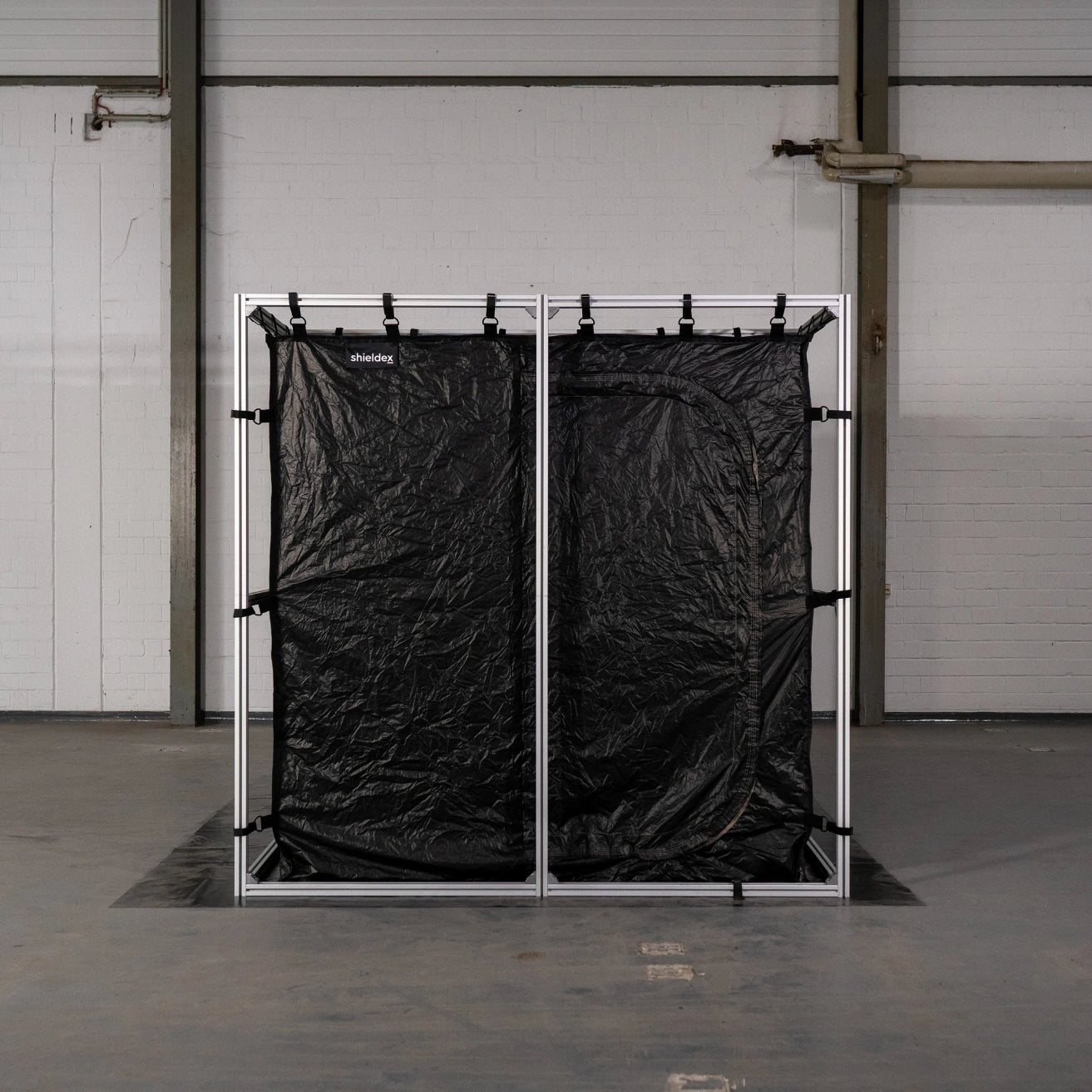
Shielded measuring rooms: EMC tents and anechoic chambers
Shielded environments are essential for precise EMC measurements in order to reduce external interference. EMC tents offer an effective solution for implementing measurement setups flexibly and with high shielding performance.
💡 EMC tents: The flexible & cost-effective solution
Shieldex EMC tents offer shielding attenuation of up to 95 dB and enable flexible measurement setups. They are a cost-effective alternative to anechoic chambers and ideal for EMC pre-compliance measurements.
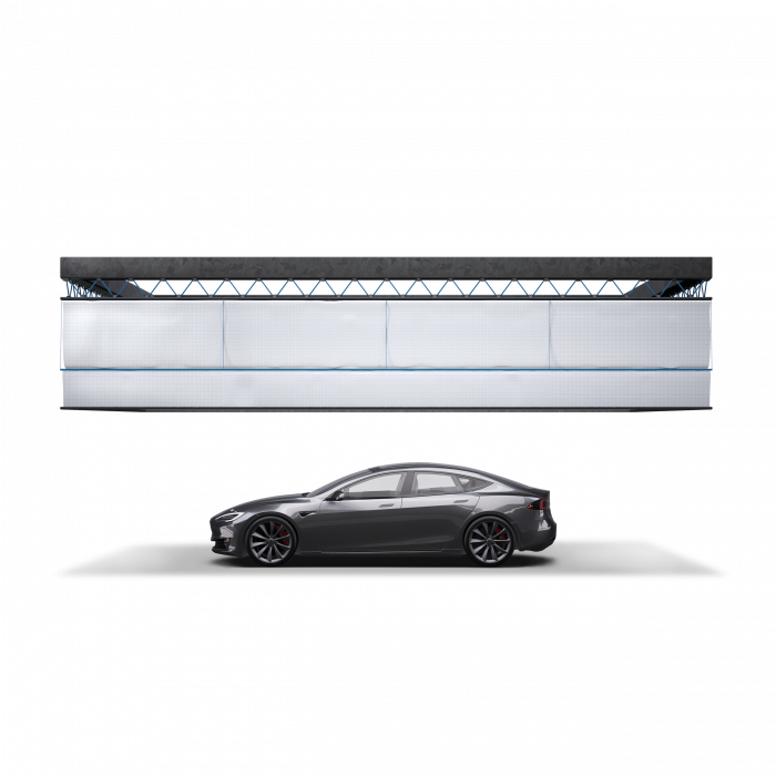
Anechoic chambers
A specially shielded anechoic chamber is required for standard-compliant measurements. These chambers consist of metallic, electrically conductive walls on the outside, which provide electromagnetic shielding from the outside world. Depending on the
design, shielding attenuations of 60 to 90 dB can be achieved.
Inside the chamber are absorbers that absorb the field energy generated by the device under test (and by antennas in immunity tests) and convert it into heat. This absorption results in reflection-free behavior that comes very close to natural free-field behavior.
The antenna is positioned at a defined distance (e.g. 3 m or 10 m) from the test specimen, which requires a correspondingly large anechoic chamber.
However, for pre-compliance measurements
there are also various options, depending on the budget, for carrying out target-oriented
measurements without a standard-compliant anechoic chamber. In this way, the effects of design changes can be quickly checked and corrected in the right direction.

Abbildung: Absorberkammer
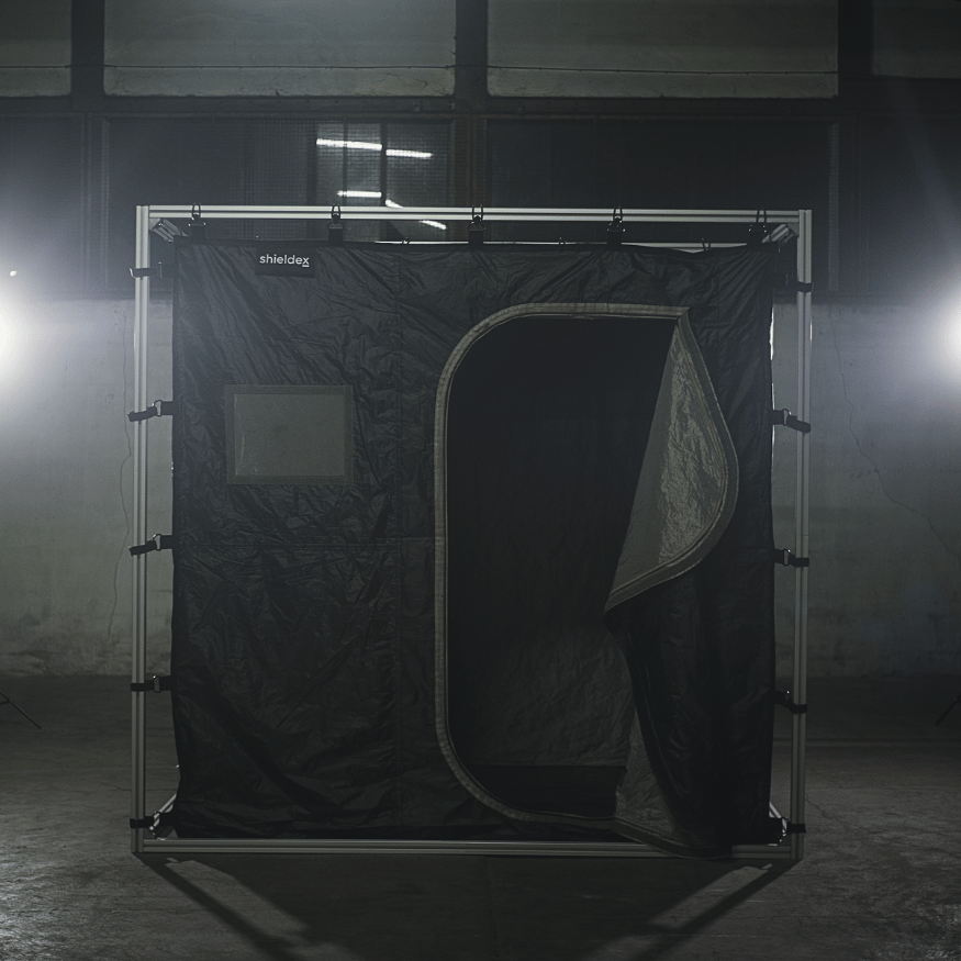
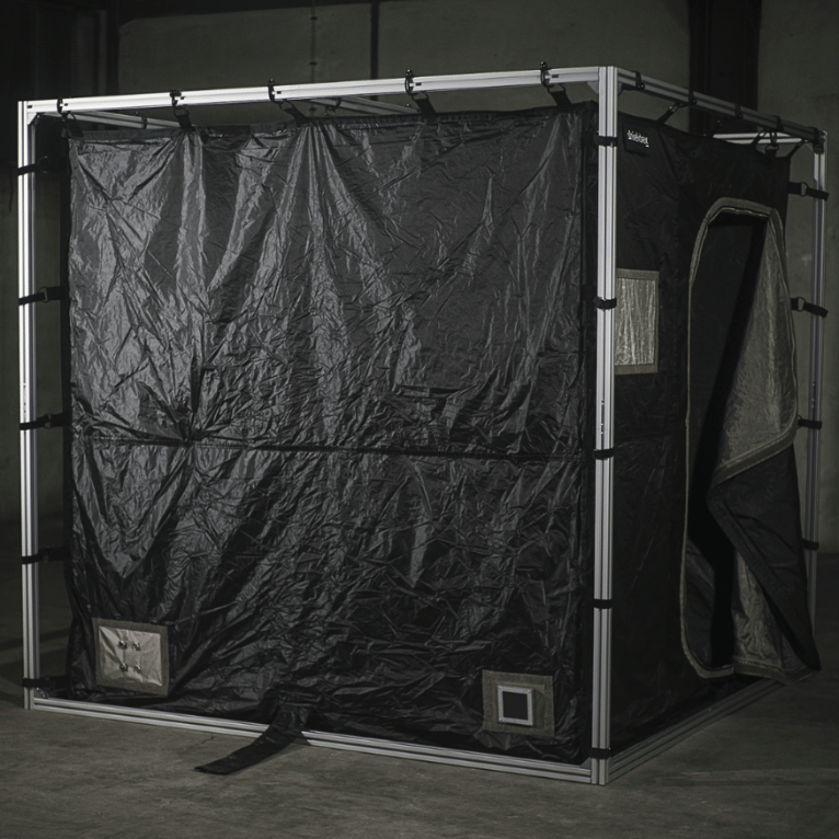
EMC tent / shielding tent / shielding tent (with and without absorber)
Shielding a test area against external radio signals (such as radio, GSM, LTE, WLAN, etc.) is relatively easy to achieve with an inexpensive EMC shielding tent. The
customized shielding tents from Shieldex offer excellent shielding
of up to 95 dB in the frequency range from 0.03 to 40 GHz. The size and features
of the tents can be customized as required and the
options are similar to those of the anechoic chambers.

EMV Zelt bei Airbus

EMV Zelt
These standards include specific guidelines for various areas of testing, such as:

What's Next?
In the era of electromobility, shielding plays a key role in the automotive industry. Shieldex solutions help manufacturers maximize performance and ensure reliable protection against electromagnetic interference.